Reworking the AI Thinker T5 – Part VI – Blinkenlights!
Reworking the AI Thinker T5 – Part VI – Blinkenlights!
Okay, now we get to the bit that everyone’s been waiting for; we’re going to connect up the LEDs. Yay!
If you remember back to the original description of the board, I mentioned that there were three LEDs (next to the ESP8266 module) which, with their current-limiting resistors, were arranged in a vaguely spoked shape (and as there are only three spokes, it’s more like an old-fashioned water valve than a bicycle wheel). Unfortunately, the folks who designed the board put the LEDs on the inside of the spokes (with the resistors on the outside), which kinda’ spoils the effect …and also makes them a little more difficult to wire up, as the cathodes are all so close together. In an earlier instalment, I added a short jumper wire between GPIO5 of the ESP8266 and the cathode of the blue LED (which is the one closest to the ESP8266), simply so that I could have some indication that the module was powered on and operational. As with most quick-and-dirty hacks, it has become permanent and, despite the fact that it’s butt-ugly, I’m not planning to change it. That leaves the two others.
 GPIO0 and GPIO2 connections
Going back to the photo of the wiring to switch K1, you can see the short jumper to the blue LED quite clearly. The spoke pointing directly at switch K2 is a green LED and the one pointing directly at the edge of the board is a red LED. It’s also clear from the photo that soldering wires to the cathodes of the two other LEDs would be quite challenging. Luckily, the drive for all three LEDs came from the QFP 8051 chip, so the cathodes of all three are wired to the pads where that unluckydevice used to sit. Equally luckily (for my shaky-handed soldering), the pad for the blue LED is between the other two and, as the blue is already connected, it gives us a little bit of extra clearance to play with when soldering wires onto the green and red pads. The original schematic didn’t identify which LED was which, but our updated (ie:- scribbled on) version has them labelled. As you can see, the drive for the red LED is wired to pad 26 and the green to pad 28, so all we need to do is run wires from spare GPIOs on the ESP to those pads and update our test progam to use them. We’re going to use the adjacent GPIO14 and GPIO12 as our drive pins (GPIO4, on the other side of the module, is also still free, but we’re going to use that later for the connection to switch K2). For GPIO14 and GPIO12, we’ll run the wires around the rather bulky (and, for us, badly placed) smoothing cap sited between the ESP module and the edge of the board, under the DHT11 sensor and directly to the QFP pads (which are on the DHT11 side of the footprint). Again, use super-glue or tiny bits of hot-glue stick, melted with the soldering iron, to hold these (quite long) wires down to the PCB.
After completion, here’s what my board looked like.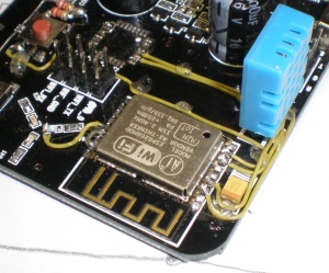 It’s starting to get a little bit crowded around that SMD capacitor, but there’s only one spare GPIO left on that side of the board anyway, so we’re not going to be adding too many more wires.
Updated code is available from the GitHub repository. The new file is named DHT11_Test_Blinken.ino and, in normal Arduino style, must be moved into a directory named DHT11_Test_Blinken to enable compilation. Note that the user_config.h file needs to be available in the same directory and that configuration changes specific to your network must be made in that file prior to compilation (ie:- your access-point SSID and password, your MQTTserver hostname and port-number, etc).
Note that if you’ve already completed the previous rework to connect switch K1 to GPIO0, you can now initiate programming mode on your T5 by turning off the power, holding down K1 and the switching the power back on again. You should be able to release K1 as soon as the board has powered up.
After programming with the “Blinken” code, the coloured LEDs will display a very brief “spinning wheel” at power-on and at all subsequent deep-sleep wake-ups.
The next instalment will cover adding K2 as a “mode control” switch, to change the function of the board at power-up time.