PS2 Controller Sketch
The ideal controller for this ROV is a wired Playstation 2 controller. Luckily they are still made and there is a library for the Arduino to talk to them. It is also possible to buy sockets for the Playstation 2 controller to plug into without having to make any modifications to the controller.
This sketch is a development to test the use of the wired Playstation 2 controller for driving a series of servos and LEDs. The Servos are stand-ins for the ESCs that would be used in reality. The LEDs are used to simulate camera triggers and status as well as pretend to be the main lights.
A more detailed article on using Playstation2 Controllers for Arduino projects is available on the "Using A Playstation 2 Controller with your Arduino Project"page.
The sketch has been set up for easy splitting into the two sections; one for the Top-Side master Arduino and one for the ROV Slave Arduino with a series of variables being sent between the two to carry the control commands.
In this case an Arduino Uno has been used.
The coding makes use of the PS2X library developed by Bill Porter. See www.billporter.info for the latest from Bill Porter and to download the library. The example sketch with the library gives an excellent demonstration of the many different ways of interacting with the controller and many functions that I was unaware existed.
The needs for this project with regards to reading the PS2 controller are fairly simple compared to what input methods are available. I have made use of;
* the .Button() function which registers when a button is pressed and held. This is useful for the camera pitch control.
* the .ButtonPressed() function which just registers when the button is pressed but does not recognise when it is held. This is useful for the toggle functions such as the camera recording on/off, the main headlights ON/OFF, and the take-a-photo button.
* the .Analog() function which is simply for reading the analogue sticks.
The names Bill Porter has given for all of the buttons and sticks are very logical and the example sketch with his PSX library makes use of them all. The diagram below identifies the labels used by the PS2X library.
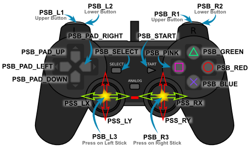
There is a variation of the above with “PSAB” substituted for the “PSB” for some of the buttons that allow the user to get input from how hard the buttons are pressed. For example PSAB_BLUE measures the amount of pressure applied to the X-button. This is very cool but not necessary for the needs of this project.
The Pin Assignments
3.3V output to PS2 red Pin
5V output to 1kΩ pull up resistors for PS2.
Pin D10 to PS2 yellow pin
Pin D11 to PS2 orange pin
Pin D12 to PS2 brown pin
Pin D13 to PS2 blue pin
Pin D2 to LED Camera Photo Trigger
Pin D3 to LED Camera Record Indicator
Pin D4 to LED Main Lights
Pin D5 to Servo Up Left
Pin D6 to Servo Up right
Pin D7 to Servo Horiz Left
Pin D8 to Servo Horiz Right
Pin D9 to Servo Cam Pitch
External 5V power supply is providing to the Servo Voltage Line
Controls for the ROV
The controls for the ROV will be
Left Stick: X-axis = Roll, Y-axis = Up/down
Right Stick: X-axis = Yaw, Y-axis = forward/back
Direction button pad left = LED Main lights On/Off toggle
Direction button pad up = Turn camera upwards
Direction button pad down = Turn camera downwards
Triangle = Start/Stop video recording
Circle = Take photo
Circuit
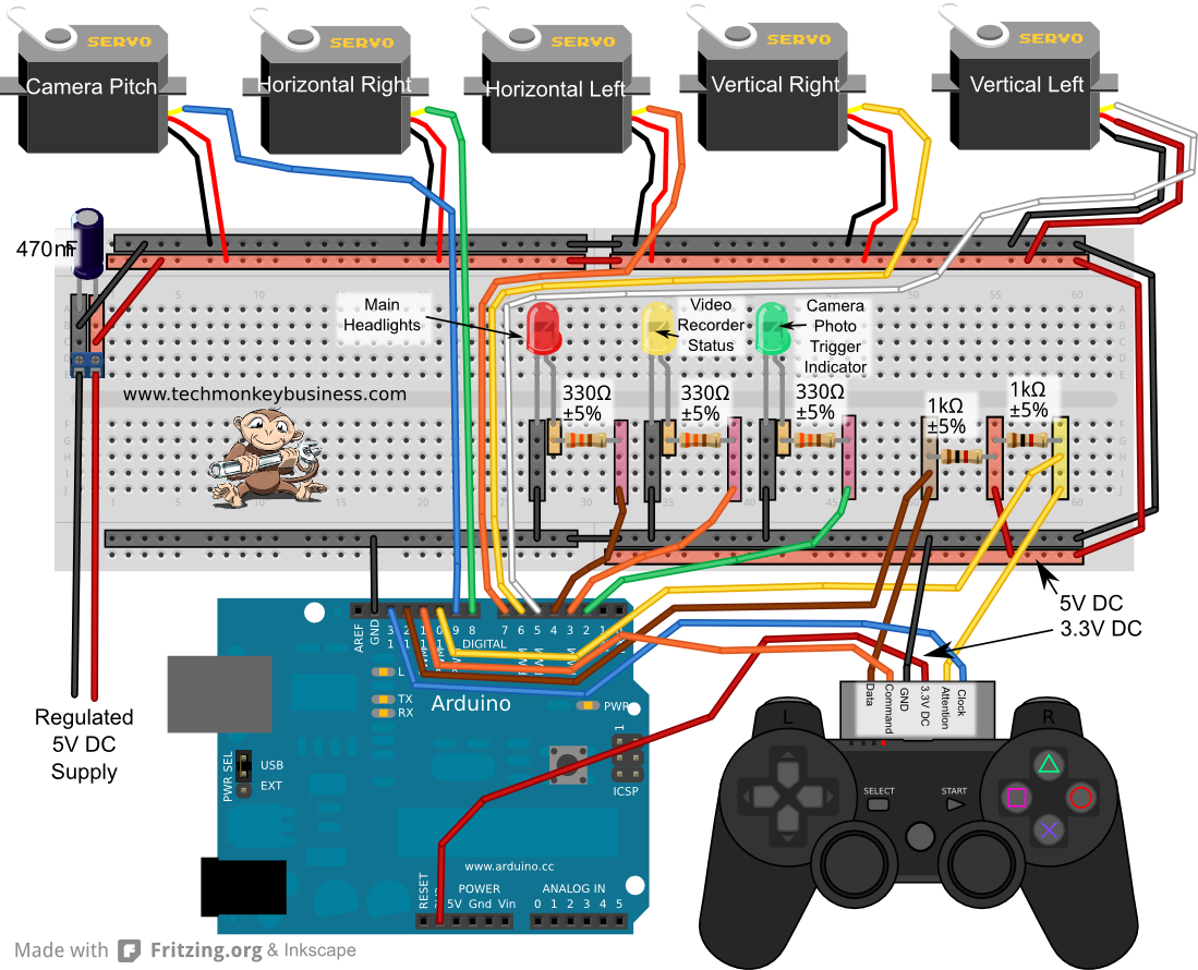
Click on the image or here for a higher resolution image.
The Code
The sketch below can be downloaded from here: ROVPS2ControlTest1.ino
You can also download the PS2X library from the following webpage: A Collection of Arduino Libraries Used in This Project.
/*
ROVPS2ControlTest1.ino

This development sketch seeks to simulate the Playstation 2 control
of the ESCs and servos of the ROV.  LEDs are used to stand in for
the main LED, the Camera recording function and photographing trigger.

Pin assignments are:

3.3V output to PS2 red Pin
5V output to 1Kohm pull up resistors for PS2.
Pin D10 to PS2 yellow pin
Pin D11 to PS2 orange pin
Pin D12 to PS2 brown pin
Pin D13 to PS2 blue pin

Pin D2 to LED Camera Photo Trigger
Pin D3 to LED Camera Record Indicator
Pin D4 to LED Main Lights

Pin D5 to Servo Up Left
Pin D6 to Servo Up right
Pin D7 to Servo Horiz Left
Pin D8 to Servo Horiz Right
Pin D9 to Servo Cam Pitch

External 5V powersupply is providing to the Servo Voltage Line

The coding pulls on the PS2X library developed by Bill Porter.
See www.billporter.info for the latest from Bill Porter and to
download the library.

While the readings from the controller could be plopped straight into
the servo commands, variable will be used to hold the values so
that it will simulate the data packages that will be sent to the
ROV arduino over the serial eventually.

The controls for the ROV will be
Left Stick - X-axis = Roll, Y-axis = Up/down
Right Stick - X-axis = Yaw, Y-axis = forward/back
Direction button pad left = LED Main lights On/Off toggle
Direction button pad up = turn camera upwards
Direction button pad down = turn camera downwards
Triangle = Start/Stop video recording
Circle = Take photo

*/


#include <Servo.h>  //For driving the ESCs and Servos
#include <PS2X_lib.h> // Bill Porter's PS2X Library

PS2X ps2x;  //The PS2 Controller Class
Servo UpLServo;  //Create servo object representing up left ESC
Servo UpRServo;  //Create servo object representing up right ESC
Servo HorizLServo;  //Create servo object representing horiz left ESC
Servo HorizRServo;  //Create servo object representing horiz right ESC
Servo CamServo;  //Create servo object representing camera pitch

const int grnLEDpin = 4;  //green LED is on Digital pin 12
const int redLEDpin = 3;  //red LED is on Digital pin 13.
const int yelLEDpin = 2;  //yellow LED is on Digital pin 2

volatile boolean CamRec;  //Camera record function toggle
volatile boolean LEDHdlts; //LED headlights on/off toggle

int ForwardVal = 0;  //Value read off the PS2 Right Stick up/down.
int YawLeftVal = 0;  //Value read off the PS2 Right Stick left/right
int UpVal = 0; //Value read off the PS2 Left Stick up/down
int RollLeftVal = 0; // Value read off the PS2 Left Stick left/right
int CamPitch = 90; //Angle of the camera servo.

int CamPhotoInd = 0; // a counter for controlling the camera trigger indicator

int upLraw = 0;  //Variables to carry the actual raw data for the ESCs
int upRraw = 0;
int HLraw = 0;
int HRraw = 0;

void setup()
{
  ps2x.config_gamepad(13,11,10,12, false, false);
  //setup pins and settings: GamePad(clock, command, attention, data, Pressures?, Rumble?)
  //We have disabled the pressure sensitivity and rumble in this instance and
  //we know the controller type so we have not bothered with the error checks
  pinMode(grnLEDpin, OUTPUT);  //Sets the grnLEDpin to output
  pinMode(redLEDpin, OUTPUT);  //Sets the redLEDpin to output
  pinMode(yelLEDpin, OUTPUT);  //Sets the yelLEDpin to output.
  CamRec = false;  //Sets the Camera default to not recording
  UpLServo.attach(5);// attaches the Up left Servo to pin 5
  UpRServo.attach(6);// attaches the Up Right Servo to pin 6
  HorizLServo.attach(7);// attaches the Horizontal Left Servo to pin 7
  HorizRServo.attach(8);// attaches the Horizontal Right Servo to pin 8
  CamServo.attach(9); // Attaches the Camera Pitch Servo to pin 9.

}

void loop()
{
  ps2x.read_gamepad(); //This needs to be called at least once a second
                        // to get data from the controller.
  if(ps2x.Button(PSB_PAD_UP))  //Pressed and held
  {
    CamPitch = CamPitch + 1; //increase the camera pitch
  }

  if(ps2x.ButtonPressed(PSB_PAD_LEFT))  //Pressed
  {
    LEDHdlts = !LEDHdlts; //Toggle the LED light flag
  }


  if(ps2x.Button(PSB_PAD_DOWN))  //Pressed and Held
  {
    CamPitch = CamPitch - 1; //increase the camera pitch
  }


  if(ps2x.ButtonPressed(PSB_GREEN))  //Triangle pressed
  {
    CamRec = !CamRec; //Toggle the Camera recording Status
  }

  if(ps2x.ButtonPressed(PSB_RED))  //Circle pressed
  {
    CamPhotoInd = 70;  //Set to indicate photo taken for about 1 second.
  }

//Analogue Stick readings
  ForwardVal = ps2x.Analog(PSS_RY);
  YawLeftVal = ps2x.Analog(PSS_RX);
  UpVal = ps2x.Analog(PSS_LY);
  RollLeftVal = ps2x.Analog(PSS_LX);

//Translate the Stick readings to servo instructions
//This would normally happen in the ROV based on the
//Stick readings sent to it from the topside Arduino
//Over the serial.
//Readings from PS2 Controller Sticks are from 0 to 255
//with the neutral being 128.  The zero positions are to
//the left for X-axis movements and up for Y-axis movements.

//Variables to carry the actual raw data for the ESCs
  upLraw = (128-UpVal)+(128-RollLeftVal)/2;  //This will be up to a value of 192
  upRraw = (128-UpVal)-(128-RollLeftVal)/2;  //This will be up to a value of 192
  HLraw = (128-ForwardVal)+(128-YawLeftVal);  //This will be up to a value of 256
  HRraw = (128-ForwardVal)-(128-YawLeftVal);  //This will be up to a value of 256

//Scale the values to be suitable for ESCs and Servos
  upLraw=map(upLraw,-193,193,0,179);
  upRraw=map(upRraw,-193,198,0,179);
  HLraw=map(HLraw,-256,256,0,179);
  HRraw=map(HRraw,-256,256,0,179);

//Write it to the Servos or ESCs

  UpLServo.write(upLraw);
  UpRServo.write(upRraw);
  HorizLServo.write(HLraw);
  HorizRServo.write(HRraw);

// Signalling that a photo has been taken.

  if(CamPhotoInd >= 1)
  {
    CamPhotoInd = CamPhotoInd - 1; //countdown for the CamIndicator
    digitalWrite(grnLEDpin,HIGH);  //Light the Green LED to indicate phototriggered
  }
  if(CamPhotoInd <= 0)
  {
    digitalWrite(grnLEDpin,LOW);  //Photo event indication over.
  }

  CamPitch = constrain(CamPitch,30,149); //keep CamPitch within the 30 - 149 boundary
  CamServo.write(CamPitch);  //Move the camera servo
  digitalWrite(redLEDpin,CamRec); //Light the redLED based on camera recording status flag
  digitalWrite(yelLEDpin,LEDHdlts); //Light the LED based on headlights status flag
  delay(15);
}