nRF905 AVR/Arduino Library/Driver
The nRF905 is a radio transceiver IC similar to the well known nRF24L01, but operates at 433/898/915MHz instead of 2.4GHz, has a much longer range and a few extra IO pins. However the nRF905 data rate is only 50Kbps compared to nRF24L01′s 2Mbps.
This library offers quite a bit of flexibility: Optional use of interrupts, 2 of the connections to the module are optional since their states can also be accessed by the ICs status register, and supports basic collision avoidance.
Download from GitHub
Documentation
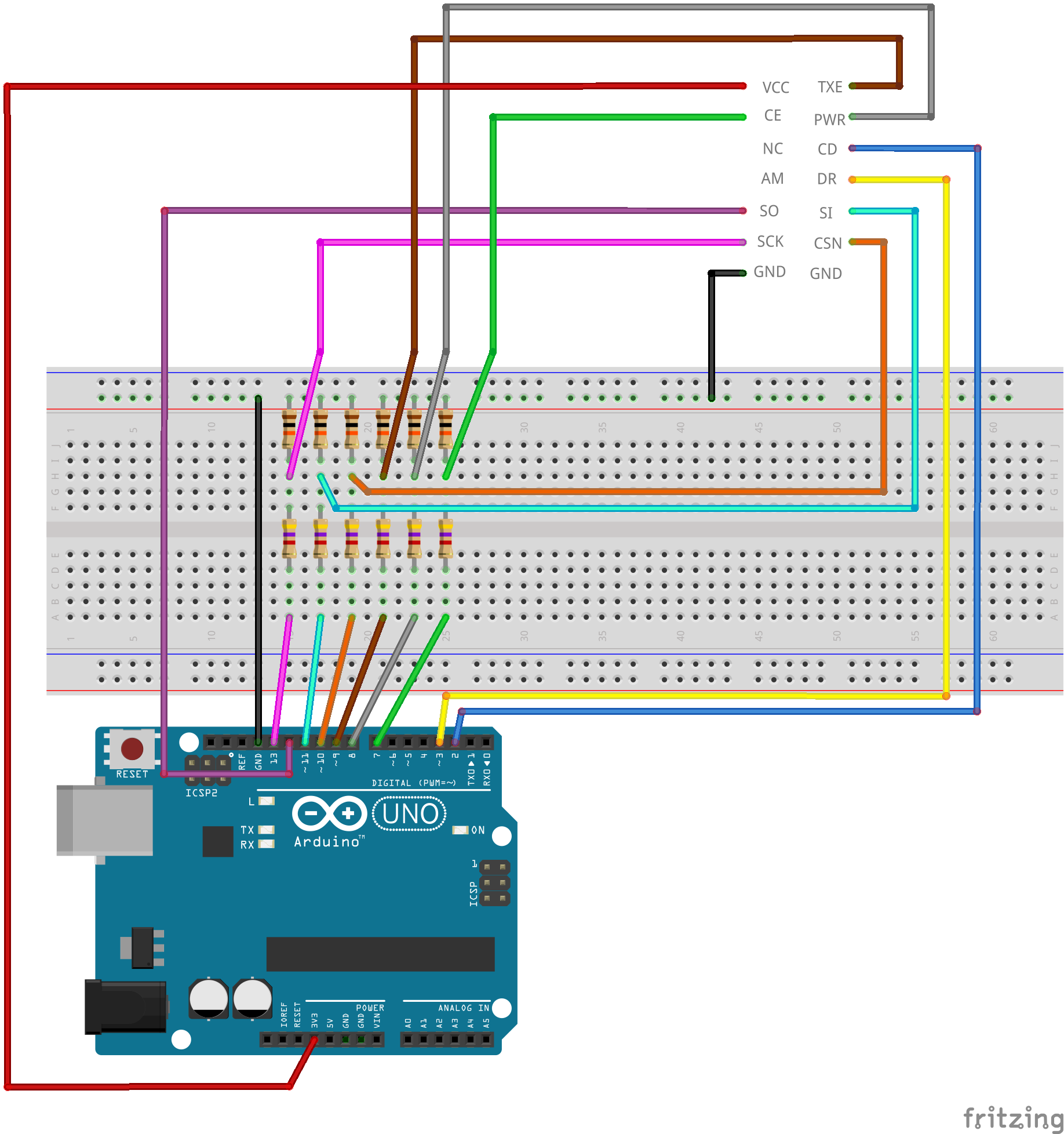
| nRF905 | ATmega48/88/168/328 | Arduino Uno | Description |
|---|---|---|---|
| VCC | 3.3V | 3.3V | Power (3.3V) |
| CE | D7 (13) | 7 | Stand by – High = TX/RX mode, Low = standby |
| TXE | B1 (15) | 9 | Transmit or receive mode – High = transmit, Low = receive |
| PWR | B0 (14) | 8 | Power up – High = on, Low = off |
| CD | D2 (4) | 2 | Carrier detect – High when a signal is detected, for collision avoidance |
| AM | - | - | Address Match – High when receiving a packet that has the same address as the one set for this device, optional since state is stored in register, not used by this library |
| DR | D3 (5) | 3 | Data Ready – High when finished transmitting/High when new data received, optional since state is stored in register, if interrupts are used this pin must be connected |
| SO | B4 (18) | 12 | SPI MISO |
| SI | B3 (17) | 11 | SPI MOSI |
| SCK | B5 (19) | 13 | SPI SCK |
| CSN | B2 (16) | 10 | SPI SS |
| GND | GND | GND | Ground |
Some of the module pin names differ from the IC pin names in the datasheet:
| Module | IC |
|---|---|
| CE | TRX_EN |
| TXE | TX_EN |
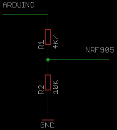
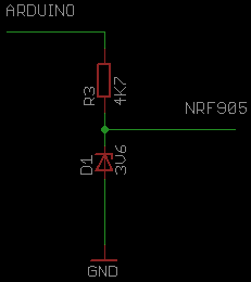
The nRF905 is not 5V compatible, so some level conversions will need to be done with the Arduino outputs, a simple voltage divider or resistor and zener diode will do the trick, only TXE, CE, PWR, SI, SCK and CSN pins need level conversion (not CD, AM, DR and SO).
| Divider | Zener |
|---|---|
 |
 |
The nRF905 has 511 channels ranging 422.4MHz – 473.5MHz in 100KHz steps on the 433MHz band and 844.8MHz – 947MHz in 200KHz steps on the 868/915MHz band (remember to check which frequencies are legal in your country!), but each channel overlaps adjacent channels so there is only a total of 170 usable channels at once.
Searching for nRF905, PTR8000 and PTR8000+ should yield some results for modules on Ebay and DealExtreme, you should be able to get 2 for around £10.
Library coding tips
- http://blog.zakkemble.co.uk/wp-content/themes/graphene/images/list-style-image.png);">You can call nRF905_receive() straight after calling nRF905_sendData(), this makes the radio go into receive mode once the payload has finished transmitting.
- http://blog.zakkemble.co.uk/wp-content/themes/graphene/images/list-style-image.png);">Calling an nRF905_set***() function will put the radio into standby mode (radio must be in standby mode to change registers), if you want it to carry on receiving you must call nRF905_receive() again.
Nitty-gritty radio stuff
Actual air data rate of nRF905 is 100Kbps, but the data is Manchester encoded which halves it to 50Kbps. The modulation is GFSK with ±50KHz deviation. The radio also adds a few extra bits of data to the address and payload; a preamble and CRC.
Transmitted packet
| Preamble 10 bits |
Address 1 or 4 bytes |
Payload 1 – 32 bytes |
CRC 0 – 2 bytes |
The CRC is used to detect errors in the received data. Having a CRC doesn’t eliminate all bad packets, there is always a small chance of a bad packet passing the CRC. Using larger CRCs helps to reduce the chance.
Transmission time
The sizes of the address, payload and CRC can be adjusted for a balance between throughput and latency.
Example configurations
| Config # | Address | Payload | CRC |
|---|---|---|---|
| Config 1 | 4 | 32 | 2 |
| Config 2 | 1 | 4 | 1 |
| Config 3 | 1 | 1 | 0 |
Throughput and latency for each configuration
| Config # | Throughput (bps) | Latency (ms) |
|---|---|---|
| Config 1 | 36940 | 6.93 |
| Config 2 | 17680 | 1.81 |
| Config 3 | 6838 | 1.17 |
Throughput is how much useful data can be sent (the payload part), assuming no delays for setting the payload.
Latency is how long it takes for the transmission to complete.
Switching from standby mode to receive or transmit mode takes max 650us and switching between receive and transmit modes takes max 550us.
Transmission time can be worked out with:
t = tstartup + tpreamble + ((Naddress + Npayload + NCRC) / BR)
tstartup is the time to switch mode as stated above (650us / 550us).
tpreamble is 200us for the 10 bit preamble.
Naddress, Npayload and NCRC are the address, payload and CRC sizes in bits.
BR is the bit rate which is 50,000.
For config 1, switching from standby to transmit:
t = 0.00065 + 0.0002 + ((32 + 256 + 16) / 50000)
t = 0.00693 seconds (6.93ms)

NRF905 QPSK Transceiver (433MHz)
NRF905 wireless module PTR8000 (+) wireless transmission module NF905SE band antenna (C3B5)
| NRF905 Module | Arduino | |
| 1 | VCC | 3V3 (from LDO) |
| 2 | TXE | Pin 5 |
| 3 | CE | Pin 6 |
| 4 | PWR | A0 |
| 5 | CLK | |
| 6 | CD | Pin 2 |
| 7 | AM | Pin 7 |
| 8 | DR | Pin 3 |
| 9 | MISO | MISO |
| 10 | MOSI | MOSI |
| 11 | SCK | SCK |
| 12 | CSN | Pin 4 |
| 13 | GND | GND |
| 14 | GND | GND |
You could visit our github page forArduino NRF905 library.
Contents[hide] |
Size

Pin Definition
- VCC ---- Power supply.
- TXE ---- RF module mode selecting.
- CE ---- Enable RF module for transmit and receive.
- PWR ---- Power up chip.
- CLK ---- Output clock, divided crystal oscillator full swing clock.
- CD ---- Carrier detect.
- AM ---- Address matched.
- DR ---- Receive and transmit ready.
- MISO ---- SPI master input slave output.
- MOSI ---- SPI mater output slave input.
- SCK ---- SPI clock.
- CSN ---- SPI enable.
- GND ---- Ground
- GND ---- Ground
Example_with_arduino

Usage
There are two examples in this code, one is sending data and another is receiving data. File:Get the code here.
Set different bands for different countries, here is very easy to change: nrf905.write_config(US); Just enter your country or area as a parameter in this function. In fact, you have choices:
| Country | Band |
|---|---|
| US | 908.42Mhz |
| EU | 868.42Mhz |
| Africa | 868.42Mhz |
| China | 868.42Mhz |
| HK | 919.82Mhz |
| Japan | 853.42Mhz |
| Australia | 921.42Mhz |
| New_zealand | 921.42Mhz |
| Brasil | 921.42Mhz |
| Russia | 896Mhz |
upload the two examples into two arduino boards, one for sending and other one for receiving:
On the receiving end, you should be able to see:
Hi, Arduino 0,
Hi, Arduino 1,
Hi, Arduino 2,
Documentation
- Nrf905 datasheet - File:Product Specification nRF905 v1.5.pdf
- Schematic - File:XL905-51-schematic.pdf
- Demo Code with atmega 16
- Code for arduino
http://blog.zakkemble.co.uk/nrf905-avrarduino-librarydriver/
The nRF905 is a radio transceiver IC similar to the well known nRF24L01, but operates at 433/898/915MHz instead of 2.4GHz, has a much longer range and a few extra IO pins. However the nRF905 data rate is only 50Kbps compared to nRF24L01′s 2Mbps.
This library offers quite a bit of flexibility: Optional use of interrupts, 2 of the connections to the module are optional since their states can also be accessed by the ICs status register, and supports basic collision avoidance.
Download from GitHub
Documentation
| nRF905 | ATmega48/88/168/328 | Arduino Uno | Description |
|---|---|---|---|
| VCC | 3.3V | 3.3V | Power (3.3V) |
| CE | D7 (13) | 7 | Stand by – High = TX/RX mode, Low = standby |
| TXE | B1 (15) | 9 | Transmit or receive mode – High = transmit, Low = receive |
| PWR | B0 (14) | 8 | Power up – High = on, Low = off |
| CD | D2 (4) | 2 | Carrier detect – High when a signal is detected, for collision avoidance |
| AM | - | - | Address Match – High when receiving a packet that has the same address as the one set for this device, optional since state is stored in register, not used by this library |
| DR | D3 (5) | 3 | Data Ready – High when finished transmitting/High when new data received, optional since state is stored in register, if interrupts are used this pin must be connected |
| SO | B4 (18) | 12 | SPI MISO |
| SI | B3 (17) | 11 | SPI MOSI |
| SCK | B5 (19) | 13 | SPI SCK |
| CSN | B2 (16) | 10 | SPI SS |
| GND | GND | GND | Ground |
Some of the module pin names differ from the IC pin names in the datasheet:
| Module | IC |
|---|---|
| CE | TRX_EN |
| TXE | TX_EN |
The nRF905 is not 5V compatible, so some level conversions will need to be done with the Arduino outputs, a simple voltage divider or resistor and zener diode will do the trick, only TXE, CE, PWR, SI, SCK and CSN pins need level conversion.
| Divider | Zener |
|---|---|
|
|
The nRF905 has 511 channels ranging 422.4MHz – 473.5MHz in 100KHz steps on the 433MHz band and 844.8MHz – 947MHz in 200KHz steps on the 868/915MHz band (remember to check which frequencies are legal in your country!), but each channel overlaps adjacent channels so there is only a total of 170 usable channels at once.
Searching for nRF905, PTR8000 and PTR8000+ should yield some results for modules on Ebay and DealExtreme, you should be able to get 2 for around £10.
Tips and things to watch out for
- You can call nRF905_receive() straight after calling nRF905_sendData(), this makes the radio go into receive mode once the payload has finished transmitting.
- Calling an nRF905_set***() function will put the radio into standby mode (radio must be in standby mode to change registers), if you want it to carry on receiving you must call nRF905_receive() again.
Nitty-gritty radio info
Actual air data rate of nRF905 is 100Kbps, but the data is Manchester encoded which halves it to 50Kbps. The modulation is GFSK with ±50KHz deviation. The radio also adds a few extra bits of data to the address and payload; a preamble and CRC.
Transmitted packet
| Preamble 10 bits |
Address 1 or 4 bytes |
Payload 1 – 32 bytes |
CRC 0 – 2 bytes |
The CRC is used to detect errors in the received data. Having a CRC doesn’t eliminate all bad packets, there is always a small chance of a bad packet passing the CRC. Using larger CRCs helps to reduce the chance.
Transmission time
The sizes of the address, payload and CRC can be adjusted for a balance between throughput and latency.
Example configurations
| Size | Config 1 | Config 2 | Config 3 |
|---|---|---|---|
| Address | 4 | 1 | 1 |
| Payload | 32 | 4 | 1 |
| CRC | 2 | 1 | 0 |
Throughput and latency for each configuration
| Config 1 | Config 2 | Config 3 | |
|---|---|---|---|
| Throughput (bps) | 36940 | 17680 | 6838 |
| Latency (ms) | 6.93 | 1.81 | 1.17 |
Throughput is how much useful data can be sent (the payload part), assuming no delays for setting the payload.
Latency is how long it takes for the transmission to complete.
Switching from standby mode to receive or transmit mode takes max 650us and switching between receive and transmit modes takes max 550us.
Transmission time can be worked out with:
t = tstartup + tpreamble + ((Naddress + Npayload + NCRC) / BR)
tstartup is the time to switch mode as stated above (650us / 550us).
tpreamble is 200us for the 10 bit preamble.
Naddress, Npayload and NCRC are the address, payload and CRC sizes in bits.
BR is the bit rate which is 50,000.
For config 1, switching from standby to transmit:
t = 0.00065 + 0.0002 + ((32 + 256 + 16) / 50000)
t = 0.00693 seconds (6.93ms)
Product Description


