Warning: "continue" targeting switch is equivalent to "break". Did you mean to use "continue 2"? in /customers/3/2/5/taillieu.info/httpd.www/templates/taillieuinfo_joomla3_rev1/functions.php on line 194 Taillieu.Info - Zigbee

Taillieu.Info

More Than a Hobby..

Zigbee

  • CC2531

  • How to create a CC2530 router

    The CC2530 is highly suitable for serving as a router. It has an external antenna which will greatly improve the range of your Zigbee network. This tutorial will explain how to create a CC2530 router packed into a nice enclosure which can be powered via any regular outlet.

    DISCLAIMER: The CC2530 router will use Mains AC so there is a danger of electrocution if not installed properly. If you don’t know how to install it, please call an electrician!

    CC2530 in an enclosure

    1. What do I need? #

    NamePricePicture
    CC2530
    OR
    CC2530 + CC2591
    The CC2530 + CC2591 is more powerful but more expensive
    +-7.50$ on AliExpress

    +-15$ on AliExpress
    CC2530
    HLK-PM03 +-2.20$ on AliExpress HLK-PM03
    Enclosure (the one used has the following dimensions: 100x68x40mm) +-2$ Enclosure
    Power cable +-2$ Power cable
    CC debugger - CC debugger
    8 female to female jumper wires - Jumper wires

    2. Flashing the CC2530 #

    The CC2530 has to be flashed with a router firmware which has to be done with a CC debugger using 6 female to female jumper wires. Pins have to connected as follows:

    CC debugger pin layout #

    CC debuggerCC2530
    1 GND
    2 VCC
    3 P2.2
    4 P2.1
    7 RST
    9 VCC

    Pin layout of various CC2530 modules #

    NamePin layoutPicture
    CC2530 CC2530 pin layout CC2530
    Webee CC2530 + CC2591 Webee CC2530 + CC2591 pin layout CC2530 + CC2591

    Flashing #

    Now the CC2530 can be flashed using the same instructions as Flashing the CC2531. The router firmwares can be found here.

    CC debugger connected to CC2530

    3. Putting it in an enclosure #

    The following steps have to be followed:

    • Drill 2 holes in the enclosure; one for the antenna, one for the power cable
    • Lay a knot in the power cable; this serves as strain relief
    • Solder the power cable on to the AC pins of the HLK-PM03
    • Use 2 female to female jumper wires to connect the VC+ pin of the HLK-PM03 to the VCC pin of the CC2530 and the VC- pin of the HLK-PM03 to the GND pin of the CC2530
    • Use double sided tape to fix the CC2530 and HLK-PM03 into the enclosure

    Result #

    1

    2

    3

    4

    CC2530 in an enclosure

    4. Done!

  • How to select and flash CC2530

    How to select a CC2530 board

    Ebay and Aliexpress offer several boards with the CC2530 chip (keyword: CC2530). You may select any board, but use the following criteria:

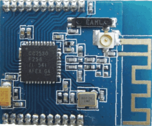
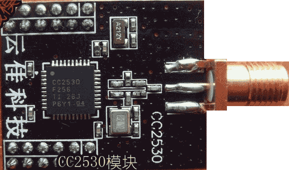
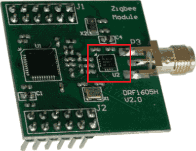
    1. The board must have the CC2530F256 chip (fig. 3). The key number here is 256 and it means 256 KB of flash memory. Most firmware was compiled for 256K memory.
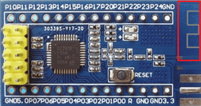
    2. The board may have many pins or contacts. If you do not have a soldering iron then select a board with headers. I would suggest to select a board where each pin has the corresponding label. The label may slightly different on different boards: P0.2, P02, P0_2 are the same pin. The board must have at least the following pins:
      1. Po.2, Po.3, P2.0 – used for a UART interface. If you plan to use this board instead CC2531 and connect to your SBC like Raspberry Pi, then you need these pins. If you’ll upload a router firmware to this board then these pins are optional.
      2. P2.1, P2.2, RST – used for uploading firmware.
      3. GND – ground.
      4. Power source (VCC) – it may be 3.3V, 5V or both. This pin can be marked by VCC only. Internally, the CC2530 chip uses the 3.3V voltage, but a manufacturer may add a voltage regulator on the board and you may use any supported voltage (3.3V or 5V, no difference). Please, read a description for this board carefully about the voltage.
    3. The board may include an additional small chip (fig.5). Most likely, this is a wireless signal amplifier. Usually these boards contain “Long range”, “RF front-end”, “RF amplifier”, “CC2591”, “RXF2401” in a description. These boards require a special firmware. I would suggest to select this board if you really have a firmware for this combination of the main chip (CC2530) and the RF front-end chip.
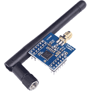
    4. The board may contain an antenna on-board (fig.2, 3, 6) or a connector for an external antenna (fig. 1, 3, 4, 5). The board with an external antenna will work better in most cases.
    5. Some boards may have a metallic shield over the main chip and/or the RF front-end. This shield protects the board from radio noises (good). But I would suggest to buy this board from a trusted vendors only because you cannot be sure about chips under this cover.
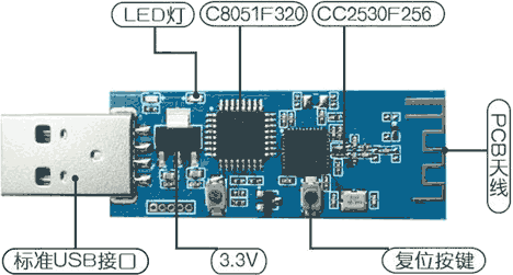
    6. Rare CC2530 based boards may include an USB interface (fig. 6). CC2530 does not have native USB support apart from CC2531. Therefore a manufacturer adds an additional chip on the board. The additional chip implements the USB interface and the CC debugger. Therefore you can upload a firmware to this board without a special debugger (CC debugger or SmartRF04EB).  Therefore it holds small space on your work table. It can be useful for developers. If you need only one CC2530 or CC2531 for a coordinator role you may save money. Please, read a description for a board carefully because this USB interface and chip may be used for another purpose. Therefore I cannot recommend this board for beginners.
    https://ptvo.info/wp-content/uploads/2018/05/cc2530_2_2-287x300.png 287w" sizes="(max-width: 203px) 100vw, 203px" style="box-sizing: border-box; border: 0px; display: block; margin: 0px auto 5px; max-width: 100%; height: auto; border-radius: 4px;"> Fig. 1 The compact board with an external antenna
    https://ptvo.info/wp-content/uploads/2018/06/CC2530-2-300x158.png 300w, https://ptvo.info/wp-content/uploads/2018/06/CC2530-2-600x316.png 600w, https://ptvo.info/wp-content/uploads/2018/06/CC2530-2-680x358.png 680w" sizes="(max-width: 245px) 100vw, 245px" style="box-sizing: border-box; border: 0px; display: block; margin: 0px auto 5px; max-width: 100%; height: auto; border-radius: 4px;"> Fig. 2 The board with the internal antenna, place for an external antenna connector and a debug interface header (compatible with the CC debugger cable, the dupont cable is not required)
    https://ptvo.info/wp-content/uploads/2018/06/CC2530-1-300x249.png 300w" sizes="(max-width: 151px) 100vw, 151px" style="box-sizing: border-box; border: 0px; display: block; margin: 0px auto 5px; max-width: 100%; height: auto; border-radius: 4px;"> Fig. 3 The compact board with the internal ceramic antenna and an external antenna connector
    https://ptvo.info/wp-content/uploads/2018/06/CC2530-3-300x177.png 300w" sizes="(max-width: 226px) 100vw, 226px" style="box-sizing: border-box; border: 0px; display: block; margin: 0px auto 5px; max-width: 100%; height: auto; border-radius: 4px;"> Fig. 4 The compact board with an external antenna. Black design.
    https://ptvo.info/wp-content/uploads/2018/06/CC2530-PA-4-300x231.png 300w" sizes="(max-width: 192px) 100vw, 192px" style="box-sizing: border-box; border: 0px; display: block; margin: 0px auto 5px; max-width: 100%; height: auto; border-radius: 4px;"> Fig. 5 The CC2530 board with the RF front-end
    cc2530 with USB (exotic)https://ptvo.info/wp-content/uploads/2018/06/CC2530-5-300x161.png 300w" sizes="(max-width: 272px) 100vw, 272px" style="box-sizing: border-box; border: 0px; display: block; margin: 0px auto 5px; max-width: 100%; height: auto; border-radius: 4px;"> Fig. 6 The CC2530 board with a USB connector and the additional 8051 chip

    Pre-requisites

    Here is an example for the most simple case when all pins are soldered on the board and have labels (fig. 1).

    1. The CC2530 board.
    2. The dupont cable (5 wires, female – female).
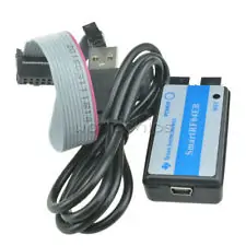
    3. The CC-debugger or SmartRF04EB (look very similar).
    4. The USB cable between the debugger and your computer (it usually comes with the debugger, USB-A <-> USB-mini).
    5. Computer with Windows.
    6. Flash Programmer V1 (V2 does not work).

    How to connect CC2530 to the debugger

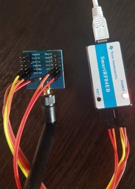
    This is simple. Use the dupont cable and connect pins on the debugger’s connector to the corresponding pin on your board.

    Note: if CC-debugger cannot detect your board, additionally try to connect the pin #2 to 3.3V.

    https://ptvo.info/wp-content/uploads/2018/06/smartrf04eb-pinout-300x165.png 300w" sizes="(max-width: 536px) 100vw, 536px" style="box-sizing: border-box; border: 0px; display: block; margin: 0px auto 5px; max-width: 100%; height: auto; border-radius: 4px;">

    https://ptvo.info/wp-content/uploads/2018/06/smartrf04eb_cc2530-215x300.jpg 215w" sizes="(max-width: 265px) 100vw, 265px" style="box-sizing: border-box; border: 0px; display: block; margin: 0px auto 5px; max-width: 100%; height: auto; border-radius: 4px;">

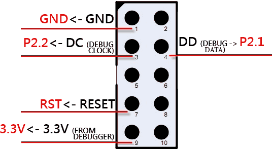
    The board from fig. 2 is compatible with a flat white cable usually shipped with CC-debugger or SmartRF04EB. This flat cable can be connected to the yellow header (the red wire should be connected to pin #1 of this header).

    https://ptvo.info/wp-content/uploads/2018/06/smartrf04eb-150x150.jpg 150w" sizes="(max-width: 225px) 100vw, 225px" style="box-sizing: border-box; border: 0px; display: block; margin: 0px auto 5px; max-width: 100%; height: auto; border-radius: 4px;">

    Note: if your board has the 5V power pin only then you must connect an external power source (5V and GND) to the corresponding pins on your board instead of 3.3V from the debugger. GND of the debugger and the power source must be connected at the same time.

    How to connect a CC-debugger to your computer

    Connect your debugger to a USB port on your computer using a standard USB cable. A new USB device should appear in Devices Manager on your computer. If you’ve installed Texas Instruments Flash Programmer before, the drivers for the new USB device will be installed automatically. You should see something like “SmartRF04EB” or “CC-debugger” in Devices Manager.

    How to select a right firmware

    Here are examples for general usage cases. All these examples may have exceptions.

    1. Select a firmware for the right chip: CC2530 in our case.
    2. If your board has a RF front-end chip then you must select a firmware for combination of the main chip and the RF chip (for example CC2530 + RXF2401). For example, CC2530ZNP-Pro-Secure_LinkKeyJoin_RXF2401.hex
    3. Select a firmware for your Zigbee network. Devices with different network parameters are incompatible (they cannot communicate). Each Zignbee network has the following key parameters:
      • Network Id (PanId).
      • Security key.
      • Radio channel number. This requirement is not strict. Many Zigbee devices may scan channels and find the correct channel number. But some Zigbee devices work with the pre-defined channel number only.
    4. Select a firmware for the device type you want to get from the CC2530 board:
      • Coordinator: it should be connected to a computer or SBC (Raspberry Pi, BananaPi, OrangePi, etc), because in most cases it operates under control of a computer. The firmware file name or a description may contain keywords: “coordinator”, “ZNP”. For example, CC2530ZNP-Pro-Secure_LinkKeyJoin.hex. The ZNP firmware is universal, because it operates under control of a computer and it may configure the board as necessary, probably for any Zigbee network.
      • Router: it works independently (not linked to a computer) and extends coverage of your Zigbee network. For example, CC2530-router.hex.

    You may download my firmware for a Xiaomi coordinator and router here.

    How to flash (upload) firmware

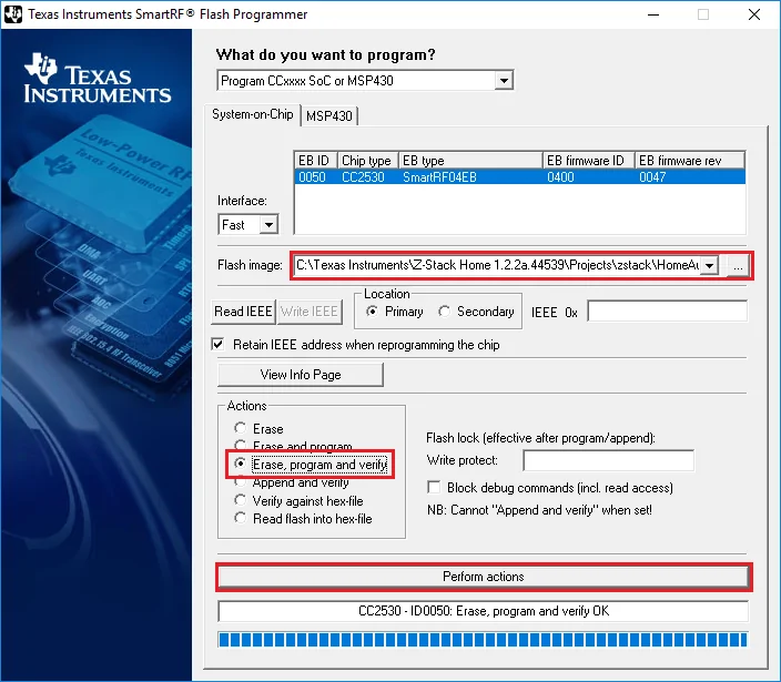
    Ok. You’ve connected the debugger and the board.

    1. Start Flash Programmer. Your debugger should be in the list. If the debugger does not appear there try to press the “Reset” button on the debugger.
    2. Select a firmware file using the “…” button.
    3. Select the following options.
    4. Click the “Perform actions” button.

    https://ptvo.info/wp-content/uploads/2018/06/flash-programmer-v1-300x262.png 300w, https://ptvo.info/wp-content/uploads/2018/06/flash-programmer-v1-600x524.png 600w, https://ptvo.info/wp-content/uploads/2018/06/flash-programmer-v1-680x594.png 680w" sizes="(max-width: 704px) 100vw, 704px" style="box-sizing: border-box; border: 0px; display: block; margin: 0px auto 5px; max-width: 100%; height: auto; border-radius: 4px;">

  • Setting up a Zigbee2mqtt gateway

    Setting up a Zigbee2mqtt gateway

    Here are the steps I performed to setup a Zigbee2mqtt gateway using a CC2530+CC2591 board and a RaspberryPI 3.
    • My RaspberryPI 3 is running
      pi@racknode:~ $ uname -a
      Linux racknode 4.19.42-v7+ #1219 SMP Tue May 14 21:20:58 BST 2019 armv7l GNU/Linux
      pi@racknode:~ $ hostnamectl
         Static hostname: racknode
               Icon name: computer
              Machine ID: 
                 Boot ID: 
        Operating System: Raspbian GNU/Linux 9 (stretch)
                  Kernel: Linux 4.19.42-v7+
            Architecture: arm
    • My Zigbee board:

       
    The steps can be structured in three groups:

    1. Flash the Z-Stack coordinator firmware on the Zigbee board
    2. Install zigbee2mqtt to run on the Raspberry Pi
    3. Setup a daemon to run zigbee2mqtt

    Flash the Z-Stack coordinator firmware on the Zigbee board

    • Connect the Zigbee board with the Raspberry (Note: this is the connection schema for flashing the firmware, while normal operation another connection schema is used.)

      NameRaspiCC2530+CC2591*
      3,3V/VCC Pin01 P12 Pin02
      GND Pin39 P12 Pin01
      RESET Pin35 P12 Pin03
      DC Pin36 P14 Pin04
      DD Pin38 P14 Pin05
      *) P12 - 12pin connector, P14 - 14 pin connector


    • Install the wiringPI library
      sudo apt-get install wiringpi
    • Install git
      pi@racknode:~ $ sudo apt-get install git
      
    • Clone the flasher repo
      git clone https://github.com/jmichault/flash_cc2531.git
    • Test the connection
      pi@racknode:~/flash_cc2531 $ ./cc_chipid
        ID = a524.
    • Get the firmware - as mentioned above I need the CC2530+CC2591 version. See https://github.com/Koenkk/Z-Stack-firmware/tree/master/coordinator/Z-Stack_Home_1.2/bin/default for the correct version.
      pi@racknode:~/flash_cc2531 $ wget https://github.com/Koenkk/Z-Stack-firmware/raw/master/
      coordinator/Z-Stack_Home_1.2/bin/default/CC2530_CC2591_DEFAULT_20190608.zip
    • Extract the archive
      pi@racknode:~/flash_cc2531 $ unzip CC2530_CC2591_DEFAULT_20190608.zip
      Archive:  CC2530_CC2591_DEFAULT_20190608.zip
        inflating: CC2530ZNP-Prod.hex
        inflating: CC2530ZNP-Prod.bin
      pi@racknode:~/flash_cc2531 $
    • Erase the CC2531 CC2530
      pi@racknode:~/flash_cc2531 $ ./cc_erase
        ID = a524.
        erase result = 00a6.
      pi@racknode:~/flash_cc2531 $
    • Write the new firmware (takes about 2-3 minutes)
      pi@racknode:~/flash_cc2531 $ ./cc_write CC2530ZNP-Prod.hex
        ID = a524.
        reading line 15490.
        file loaded (15497 lines read).
      writing page 128/128.
      verifying page 128/128.
       flash OK.
      pi@racknode:~/flash_cc2531 $ cd ..
      pi@racknode:~ $

    Install zigbee2mqtt to run on the Raspberry Pi

    Steps based on
    My steps were
    • Connect the Zigbee board with the Raspberry for operation mode

      NameRaspiCC2530+CC2591*
      3,3V/VCC Pin01 P12 Pin02
      GND Pin39 P12 Pin01
      TX (R→Z) Pin08 P12 Pin07
      RX (R←Z) Pin10 P12 Pin08
      *) P12 - 12pin connector


    • Enable UART and disable UART use for Bluetooth by adding following lines to /boot/config.txt
      pi@racknode:~ $ sudo vi /boot/config.txt
      
      enable_uart=1
      dtoverlay=pi3-disable-bt
      
    • Disable modem system
      sudo systemctl disable hciuart
    • Remove the serial console entry from /boot/cmdline.txt
      Before
      pi@racknode:~ $ cat /boot/cmdline.txt
      dwc_otg.lpm_enable=0 console=serial0,115200 console=tty1 root=...
      
      After
      pi@racknode:~ $ cat /boot/cmdline.txt
      dwc_otg.lpm_enable=0 console=tty1 root=...
      
    • Reboot the Raspberry
    • Installing the node.js 10.0 repo and install node.js
      pi@racknode:~ $ sudo curl -sL https://deb.nodesource.com/setup_10.x | sudo -E bash -
      ... and install node.js
      pi@racknode:~ $ sudo apt-get install -y nodejs
    • Clone the zigbee2mqtt repo
      pi@racknode:~ $ sudo git clone https://github.com/Koenkk/zigbee2mqtt.git /opt/zigbee2mqtt
      ... and change own to pi
      pi@racknode:~ $ sudo chown -R pi:pi /opt/zigbee2mqtt
    • Install the dependencies
      pi@racknode:~ $ cd /opt/zigbee2mqtt
      
      prebuild-install WARN install No prebuilt binaries found 
      (target=10.17.0 runtime=node arch=arm libc= platform=linux)
      make: Entering directory '/opt/zigbee2mqtt/node_modules/zigbee-herdsman/
      node_modules/@serialport/bindings/build'
        CXX(target) Release/obj.target/bindings/src/serialport.o
        CXX(target) Release/obj.target/bindings/src/serialport_unix.o
        CXX(target) Release/obj.target/bindings/src/poller.o
        CXX(target) Release/obj.target/bindings/src/serialport_linux.o
        SOLINK_MODULE(target) Release/obj.target/bindings.node
        COPY Release/bindings.node
      make: Leaving directory '/opt/zigbee2mqtt/node_modules/zigbee-herdsman/
      node_modules/@serialport/bindings/build'
      
      > serialport@8.0.1 postinstall /opt/zigbee2mqtt/node_modules/zigbee-herdsman/
      node_modules/serialport
      > node thank-you.js
      
      Thank you for using serialport!
      If you rely on this package, please consider supporting our open collective:
      > https://opencollective.com/serialport/donate
      
      
      npm WARN optional SKIPPING OPTIONAL DEPENDENCY: fsevents@1.2.9 (node_modules/
      zigbee-herdsman/node_modules/fsevents):
      npm WARN notsup SKIPPING OPTIONAL DEPENDENCY: Unsupported platform for 
      fsevents@1.2.9: wanted {"os":"darwin","arch":"any"} (current: {"os":"linux","arch":"arm"})
      npm WARN optional SKIPPING OPTIONAL DEPENDENCY: fsevents@1.2.9 (node_modules/
      fsevents):
      npm WARN notsup SKIPPING OPTIONAL DEPENDENCY: Unsupported platform for 
      fsevents@1.2.9: wanted {"os":"darwin","arch":"any"} (current: {"os":"linux","arch":"arm"})
      
      added 1356 packages from 856 contributors and audited 877179 packages in 220.282s
      found 3 high severity vulnerabilities
        run `npm audit fix` to fix them, or `npm audit` for details
    • Fix the mentioned issues
      pi@racknode:/opt/zigbee2mqtt $ npm audit fix
      npm WARN Dit e-mailadres wordt beveiligd tegen spambots. JavaScript dient ingeschakeld te zijn om het te bekijken..1 requires a peer of typescript@>=2.8.0 || >= 3.2.0-dev || >= 3.3.0-dev || ↵
      >= 3.4.0-dev || >= 3.5.0-dev || >= 3.6.0-dev || >= 3.6.0-beta || >= 3.7.0-dev || >= 3.7.0-beta but ↵
      none is installed. You must install peer dependencies yourself.
      npm WARN optional SKIPPING OPTIONAL DEPENDENCY: fsevents@1.2.9 (node_modules/↵
      zigbee-herdsman/node_modules/fsevents):
      npm WARN notsup SKIPPING OPTIONAL DEPENDENCY: Unsupported platform for fsevents@1.2.9: ↵
      wanted {"os":"darwin","arch":"any"} (current: {"os":"linux","arch":"arm"})
      npm WARN optional SKIPPING OPTIONAL DEPENDENCY: fsevents@1.2.9 (node_modules/fsevents):
      npm WARN notsup SKIPPING OPTIONAL DEPENDENCY: Unsupported platform for fsevents@1.2.9: ↵
      wanted {"os":"darwin","arch":"any"} (current: {"os":"linux","arch":"arm"})
      
      updated 2 packages in 52.752s
      fixed 3 of 3 vulnerabilities in 877319 scanned packages
      pi@racknode:/opt/zigbee2mqtt $
      
    • Enter your configuration in /opt/zigbee2mqtt/data/configuration.yaml
      vi data/configuration.yaml
      Enter your settings 
      # MQTT settings
      mqtt:
        # MQTT base topic for zigbee2mqtt MQTT messages
        base_topic: zigbee2mqtt
        # MQTT server URL
        server: 'mqtt://localhost'
        # MQTT server authentication, uncomment if required:
        # user: my_user
        # password: my_password
      # CC2590 is connected to serial line
      serial:
        port: /dev/ttyAMA0
      advanced:
        baudrate: 115200
        rtscts: false 
      
    • Start zigbee2mqtt
      pi@racknode:/opt/zigbee2mqtt $ npm start
      
      > zigbee2mqtt@1.7.1 start /opt/zigbee2mqtt
      > node index.js
      
      Logging to directory: '/opt/zigbee2mqtt/data/log/2019-11-30.16-53-43'
      Starting zigbee2mqtt version 1.7.1 (commit #b459c35)
      Starting zigbee-herdsman...
      zigbee-herdsman started
      Coordinator firmware version: '{"type":"zStack12","meta":{"transportrev":2,↵
      "product":0,"majorrel":2,"minorrel":6,"maintrel":3,"revision":20190608}}'
      Currently 0 devices are joined:
      `permit_join` set to  `true` in configuration.yaml.
      Allowing new devices to join.
      Set `permit_join` to `false` once you joined all devices.
      Zigbee: allowing new devices to join.
      Connecting to MQTT server at mqtt://xxx.xxx.xxx
      Connected to MQTT server
      MQTT publish: topic 'zigbee/bridge/state', payload 'online'
      MQTT publish: topic 'zigbee/bridge/config', payload '{"version":"1.7.1",↵
      "commit":"b459c35","coordinator":{"type":"zStack12","meta":{"transportrev":2,↵
      "product":0,"majorrel":2,"minorrel":6,"maintrel":3,"revision":20190608}},↵
      "log_level":"info","permit_join":true}'

    Setup a daemon to run zigbee2mqtt

    based on zigbee2mqtt - 5. (Optional) Running as a daemon with systemctl
    • Create a zigbee2mqtt service
      sudo vi /etc/systemd/system/zigbee2mqtt.service
      enter
      [Unit]
      Description=zigbee2mqtt
      After=network.target
      
      [Service]
      ExecStart=/usr/bin/npm start
      WorkingDirectory=/opt/zigbee2mqtt
      StandardOutput=inherit
      StandardError=inherit
      Restart=always
      User=pi
      
      [Install]
      WantedBy=multi-user.target
      
    • Verify that it works
      pi@racknode:/opt/zigbee2mqtt $ sudo systemctl start zigbee2mqtt
      pi@racknode:/opt/zigbee2mqtt $ sudo systemctl status zigbee2mqtt
      ● zigbee2mqtt.service - zigbee2mqtt
         Loaded: loaded (/etc/systemd/system/zigbee2mqtt.service; disabled; ↵
         vendor preset: enabled)
    •    Active: active (running) since Tue 2019-12-03 08:35:46 CET; 7s ago
       Main PID: 626 (npm)
          Tasks: 23 (limit: 4915)
         CGroup: /system.slice/zigbee2mqtt.service
                 ├─626 npm
                 ├─643 sh -c node index.js
                 └─644 node index.js
      
      Dec 03 08:35:46 racknode systemd[1]: Started zigbee2mqtt.
      Dec 03 08:35:50 racknode npm[626]: > zigbee2mqtt@1.7.1 start /opt/zigbee2mqtt
      Dec 03 08:35:50 racknode npm[626]: > node index.js
      Dec 03 08:35:53 racknode npm[626]: [..] Logging to directory: '/opt/zigb
      Dec 03 08:35:53 racknode npm[626]: [..] Starting zigbee2mqtt version 1.7
      Dec 03 08:35:53 racknode npm[626]: [..] Starting zigbee-herdsman...
    • Configure the autostart of the service
      pi@racknode:/opt/zigbee2mqtt $ sudo systemctl enable zigbee2mqtt.service
      Created symlink /etc/systemd/system/multi-user.target.wants/zigbee2mqtt.service ↵
      → /etc/systemd/system/zigbee2mqtt.service.
    • Reboot the Raspberry to verify your setup
      pi@racknode:/opt/zigbee2mqtt $ sudo reboot
      Connection to racknode closed by remote host.
      Connection to racknode closed.
      
      $ ssh pi@racknode
      Linux racknode 4.19.66-v7+ #1253 SMP Thu Aug 15 11:49:46 BST 2019 armv7l
      
      The programs included with the Debian GNU/Linux system are free software;
      the exact distribution terms for each program are described in the
      individual files in /usr/share/doc/*/copyright.
      
      Debian GNU/Linux comes with ABSOLUTELY NO WARRANTY, to the extent
      permitted by applicable law.
      Last login: Tue Dec  3 08:42:26 2019 from 10.0.0.171
      pi@racknode:~ $ sudo journalctl -u zigbee2mqtt.service -f
      -- Logs begin at Thu 2016-11-03 18:16:43 CET. --
      [..] Started zigbee2mqtt.
      [..] > zigbee2mqtt@1.7.1 start /opt/zigbee2mqtt
      [..] > node index.js
      [..] Logging to directory: '/opt/zigbee2mqtt/data/log/2019-12-03.08-44-14'
      [..] Starting zigbee2mqtt version 1.7.1 (commit #b459c35)
      [..] Starting zigbee-herdsman...
      [..] zigbee-herdsman started
      [..] Coordinator firmware version: '{"type":"zStack12","meta":{"transportrev":2,↵
           "product":0,"majorrel":2,"minorrel":6,"maintrel":3,"revision":20190608}}'
      [..] Currently 1 devices are joined:
      [..] 0x00158d00029acb06 (0x00158d00029acb06): MFKZQ01LM - Xiaomi Mi/Aqara smart ↵
           home cube (EndDevice)
      [..] `permit_join` set to  `true` in configuration.yaml.
      [..] Allowing new devices to join.
      [..] Set `permit_join` to `false` once you joined all devices.
      [..] Zigbee: allowing new devices to join.
      [..] Connecting to MQTT server at mqtt://mqtt.thomo.de
      [..] Connected to MQTT server
      [..] MQTT publish: topic 'zigbee/bridge/state', payload 'online'
      [..] MQTT publish: topic 'zigbee/0x00158d00029acb06', payload '{"battery":31,↵
           "voltage":2825,"linkquality":18,"angle":10.55,"side":3}'
      [..] MQTT publish: topic 'zigbee/bridge/config', payload '{"version":"1.7.1",↵
           "commit":"b459c35","coordinator":{"type":"zStack12","meta":{"transportrev":2,↵
           "product":0,"majorrel":2,"minorrel":6,"maintrel":3,"revision":20190608}},↵
           "log_level":"info","permit_join":true}'
      ^C
      pi@racknode:~ $

    Links

    • https://www.zigbee2mqtt.io/